|
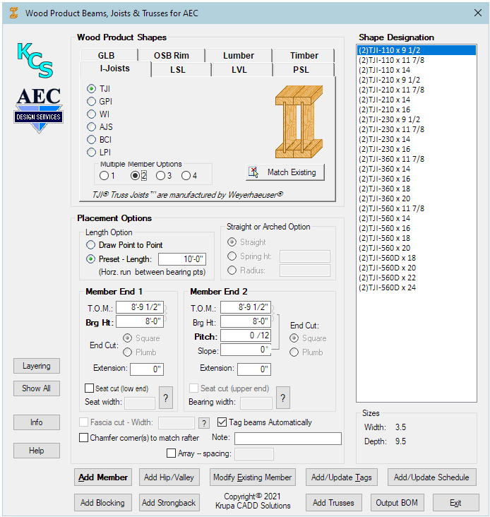
This module (formerly Wood Product Beams and Joists for AEC) provides an easy way to create wood beams, joists, rafters, plates, hips and valleys, along with tags and beam schedule, using AutoCAD Architecture (ACA) or MEP. This module provides not only the members, but also the MVBlock (tag), and Schedules. All this is contained in one dialog, accessed by one command - no need to access various palettes and ribbon tabs. This module may be used with or without the KCS Productivity Pack for AEC. This module now also provides Trusses, included on the ribbon:
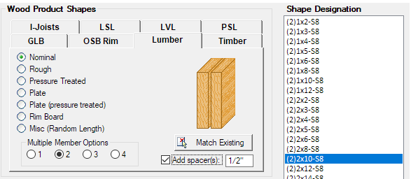
All standard lumber sizes are available, in nominal, rough, and pressure treated varieties, along with engineerd wood product members as provided by the major manufacturers. A multiple member option is provided for all member types that allow it. This module greatly simplifies the process of defining and placing these members. Select the member you need, specify the Bearing Ht. elevations, and click Add Member to draw it. Width and Depth of the selected beam are shown for reference. Length may be drawn on screen, as you would a line or a wall, or may be pre-specified. Arched beams (possible for GluLam beams only) may be specified by either the Radius, if known, or the Spring Height. Arched beams are very difficult to create in standard ACA, but here it can be easily done. Normal procedure would be to start with End 1, usually the Brg Ht but alternately the T.O.M. (Top of Member), depending on what you are doing. Values entered here are automatically applied to End 2. "Sandwiched" headers may be created with Nominal or Pressure Treated lumber. The option to add spacer(s) is enabled for these member types when the Multiple Member Option is chosen. The spacer is normally 1/2" (the default value) but may be set as required. Note that the resulting shape name then includes a "-S", followed by a number to denote the space value (8 means 8/16, for 1/2", etc.). This allows you to have spaced and non-spaced members with no confusion between the two.
This button
allows you to select a member already placed in your drawing. The dialog
will re-display with its shape selected (with the correct tab and group
selected), and also with the placement options set to match the selected
beam. Several option govern how a beam is placed at Add Member:
If you are using a drawing system that sets the Elevation system variable, note that the current elevation will be added to whatever you specify as the framing member Bearing Height. This feature allows you to create a fascia cut and soffit at the end of a rafter. This option is enabled only when the member is sloped and has an extension at the lower end. The result is not visible in plan, but will show in a 3D view.
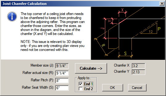
Chamfer Corner(s) to Match Rafter
The chamfer may be applied to either or both ends. The result is not visible in plan, but will show in a 3D view. A how-to is available here.
Justification
This button will allow you to modify the properties of any one or more existing beams to match the style, BrgHt, and arch properties (if any), as currently set in the dialog. The beam will retain its endpoints, except as modified by the current BrgHt setting. Any preset length in the dialog will be ignored. Hint: It's usually helpful to to use Match Existing on the beam to obtain its current values, then change whatever you wish before applying this command.
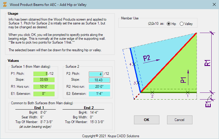
This button allows you to place a hip or valley, using the specifications currently entered. That information will be transferred to a secondary dialog and applied to Surface 1. If Surface 2 is to have a different pitch, its run will be adjusted accordingly.
Add
Strongback
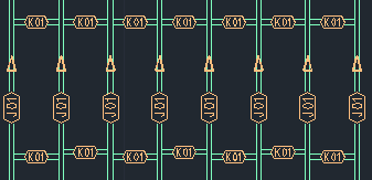
Tags may be placed on members automatically as you draw them, or they may be placed on members already drawn by using the Add/Update Tags button. Tags are automatically assigned a prefix, depending on the type of member, and how it is being used (J for joist, R for rafter, etc., according to standard practice. Tag numbers are incremented automatically for each unique member, with respect to its physical properties and its elevation, and its prefix. Number starts at 01 for each prefix used. Every time a member is tagged, all previously tagged members are checked, and if a match is found, that number is used for the current member. Thus different lengths of the same member shape get different numbers, and different elevations of the same member also get different numbers. Previously drawn members may be copied, moved in elevation, and stretched in length before tagging. However, if you change one of multiple beams that are already tagged, you should re-tag it to avoid having the same number for two different beams. You can update the tag by simply tagging it again. The Tag Beams Automatically option will speed up your work when placing new beams and is recommended, unless you want more control over which beams get what numbers. It is also better to turn this off if members are to be trimmed, such as when trimming common rafters to a hip or valley, as this will create members with varying lengths. Note that the
members, tags, and schedule must all reside in the same drawing. Xrefs
are not supported.
To create a schedule, once you have placed and
tagged members, click the Add/Update Schedule button. You may chose
either option, or both. Click OK and place the schedule(s) as
desired. If you later add more members, simply click the Add/Update Schedule
button to update the schedule(s). If you have opted for both versions, you will
not be prompted when updating again - it will just update both. If both ends of the member are at the same height, T.O.M. and BRG HT for END2 will be blank, for easier reading. (The arrow near the member tag indicates which end is which.) Note that for arched beams, the radius is given here regardless of whether it was specified by Radius or by Spring Ht, as needed for fabricating the beam. Note also that the length given is the arc length of the beam. Pitch for
Hips and Valleys Short Form:
Select a Woodbeam or Truss schedule to be exported to an Excel Spreadsheet. The schedule is pre-formatted and ready for printing. Multiple pages will have a header on each page.
This option will allow you to find the member(s) in a selected row of a Woodbeam or Truss schedule.
This option will allow you to examine the properties of a Woodbeam or Truss schedule. Here you will see the properties that appear in the schedule.
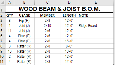
A BOM differs from a schedule as follows, per common
real world practice: * Lumber is rounded up to 2' lengths * Engineered material is rounded up to 1' lengths * Multiple members (ex: (2)2x10) are counted as two 2x10s, etc.) * Lumber pieces shorter than 12' are "consolidated" into longer pieces (two 8' lengths become one 16' length, etc.) * Rim Boards and Misc lumber are tallied as "Random Length" totals rather than pieces. The schedule is pre-formatted and ready for printing. Multiple pages will have a header on each page.
If you happen to have either of these overrides set (not commonly done), this program will restore their value after the temporary change. So this will NOT interfere with your normal layering. In addition, if you have set any other overrides - perhaps Status, or some custom override - that override will also be applied to the resulting layer. Note that this program uses layer keys STRUCTBEAM and STRUCTBEAMIDEN, so whatever properties you have set up for them in the current Layer Key Style will govern, whether you choose to use our member overrides or not. Your layer standard does need to include the Minor1 and Minor2 overrides for this feature to work. This feature does not modify your layer key style, and Layer Key Overrides are immediately reset to the way the were before placing the member.
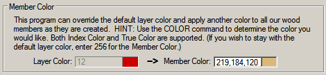
When working in viewports, the layer to be created (as described above) will be created Frozen in all other viewports. This avoids needing to freeze it in other viewports manually. If you have a viewport set up for a 3D view, you will most likely want to see the wood beam elements on all layers. This can be easily done by clicking the Show All button when in that viewport. Member color can also be controlled in this dialog. As seen below, it is set to a color intended to represent wood when seen in a 3D shaded view. The color is applied to the member as it is created - it does not affect the layer color.
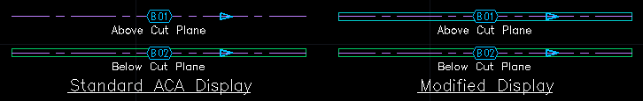
Members placed by this program will assume the same standard ACA display properties as any beams. Most significantly, when placed below the drawing current plane they will display their outlines; when placed above they display the axis line only. This may be just what you want, but if you would rather see the outline for all members there is a way to achieve this:
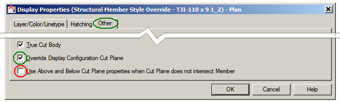
2. If not checking the Override, clicking that button (circled above) will take you to the following dialog. Or, to modify only the style or member, click the check box to take you to the same dialog. In the Properties screen (Layer/Color/Linetype tab), Above Cut Plane Visible is turned off by default. Turn the light bulb on by clicking on it. Here is the display, before and after the modification: I-Joist Display I-Joists, being made of three components, require an extra step, as just doing the above would result in lines showing for the web as well as the outline. Make sure Comp 2 & 3 are both turned off. Then go to the Other tab and change two check boxes as shown below. Doing so will have the side effect of displaying the member in its assigned color (see Member Color below) rather than the standard color of the style definition. If this matters to you, you might want to perform this step for each style.
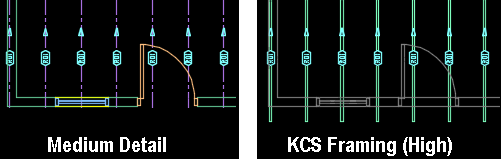
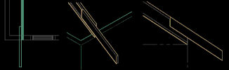
Two optional Display Configurations are now provided, as an easier (and usually preferable) way to achieve a desired appearance to your Framing plans. The two configs are KCS Framing (High) for members above the cut plain (typically Ceiling and Roof), and KCS Framing (Low) for members below the cut plain (typically Floor framing). When using either of these, architectural objects (walls, doors, etc.) will display as "screened". The appearance of these objects is controlled by the properties of the A-Anno-Scrn layer. This is a default ACA layer - you may change it's properties as desired (Hint: do so in your template file). The framing members will display as outlines, rather than axis lines, in all cases, with tags. The above sample shows some rafters, with a 10" extension, that have had a Fascia cut applied. Note that when displayed as an axis line, the extension is truncated. There seems to be no way to avoid this, but when the members are displayed as outlines as in the KCS Framing (High) config, they display properly. Here, the A-Anno-Scrn layer color has been changed from the default 250 to 252.
For any problems, critiques, or kudos, please contact kcs@krupacadd.com. We'd like to hear from you.
3.1
-
Updated for R2027 1.71 - Tag updating fixed 1.70 - Update for R2017 1.60 - Chamfer Corners added, Display Configs added 1.50 - Updated for R2016 1.40 - Fascia cut added 1.30 - Updated for R2015 1.20 - Updated for R2014 1.00 - Initial release (R2010 - R2013) |
||||||||||||||||


 The Wood Beam
& Joist Schedule is a custom KCS schedule created specially for this
module. Text styles used are the same as used by ACA in other schedules and may
be easily modified by the STYLE command according to your preferences.
The Wood Beam
& Joist Schedule is a custom KCS schedule created specially for this
module. Text styles used are the same as used by ACA in other schedules and may
be easily modified by the STYLE command according to your preferences..PNG)
 An
optional
feature of this program is the ability to place each member, along with
its tag, on special layers for each (according to it's purpose). This is
done through the use of Layer Key Overrides, which it sets temporarily
as needed. The Minor 1 and Minor 2 overrides are used. These overrides
are part of any Layer Key Style based on "AIA Layer Guidelines
version 3", or "NCS 5.0". This option is
accessed via the Layers button on the main dialog.
An
optional
feature of this program is the ability to place each member, along with
its tag, on special layers for each (according to it's purpose). This is
done through the use of Layer Key Overrides, which it sets temporarily
as needed. The Minor 1 and Minor 2 overrides are used. These overrides
are part of any Layer Key Style based on "AIA Layer Guidelines
version 3", or "NCS 5.0". This option is
accessed via the Layers button on the main dialog.  When
placing members with this option in effect, you will be prompted for
your choice of override for the Minor 1 field (to follow
"S-Beam"), or for none at all. This way you can differentiate
between members by layer, to allow visibility control for various plans.
You may add and/or remove LKO's from the list, for whatever works best
for you. The program will remember the last selected LKO. Tags will ways be on
that same layer but with "-Iden" added for the Minor 2 field.
When
placing members with this option in effect, you will be prompted for
your choice of override for the Minor 1 field (to follow
"S-Beam"), or for none at all. This way you can differentiate
between members by layer, to allow visibility control for various plans.
You may add and/or remove LKO's from the list, for whatever works best
for you. The program will remember the last selected LKO. Tags will ways be on
that same layer but with "-Iden" added for the Minor 2 field. 
 1.
Select and right-click
a desired member to modify, and select either Edit Style Display or Edit
Object display, depending on what you wish to do. Either choice will
allow you to modify the display of all members, if you wish. To do so, leave
the Override box unchecked and click the button at the upper right (in
the Display Properties tab).
1.
Select and right-click
a desired member to modify, and select either Edit Style Display or Edit
Object display, depending on what you wish to do. Either choice will
allow you to modify the display of all members, if you wish. To do so, leave
the Override box unchecked and click the button at the upper right (in
the Display Properties tab).  OR
OR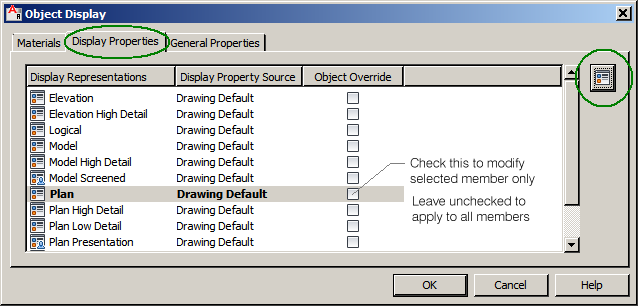
.png)