|
Representative Projects This page shows of sampling of projects done for a variety of clients, for some idea of what KCS can do.
The client has fast food establishments all over the world. The system created allows them to place their standard equipment items in the plan drawing for a new franchise, then tag each piece of equipment, and create either (or both) of two types of schedules. Each equipment block name is keyed to a database
entry. This allows tagging the equipment correctly by simply clicking on it.
Schedules are also created using information from the database. The image at
right shows some equipment with tags, plus a short-form schedule. A long-form
schedule is shown below. (Click on
the images to see full size, with additional info.)
Note: This project was done using an Excel data file created and maintained by the client.
The client wanted to extract a count of approved blocks in a drawing and output the results to an Excel file. Only approved blocks (those listed in a database) are included. The report includes information obtained from the database for each block. The client wants the report to compare the current extract with the previous extract, and show any differences. He also wants to retain the results of each extract, regardless of how many were done. The extract includes blocks contained in xrefs (provided they are loaded and inserted on a layer that is not frozen), including nested xrefs. (Click on the image to see full size, with additional info.)
The client, Centex Homes, is a large home builder that needs to create window elevations, including window assemblies, that accurately reflect the options the company offers. The dialog box is highly interactive, with sections being enabled or disabled according to various choices made. The image also updates according to those choices. This allows windows ranging from simple to complex to be created very intuitively. (Click the image to see a series of images.) The setting shown have been saved to a data file, by Catalog and Elevation name. Any changes to specifications result in a new elevation to be saved. Import/Export and Delete options are provided.
The client manufactures "showers" that are used for cleaning in paper manufacturing. They have a few basic configurations where the specifications can vary widely according to each individual application. Although the drawings were done using not-to-scale templates, calculating all the values necessary for creating the shower was a time-consuming process, involving numerous complex formulas and lookup tables. The solution was to create an easy to use dialog box for inputting the known specifications. The program then handles all the lookups and calculations, and creates a set of three drawings with the resulting values plugged in. Some values are in dimensions, some are in the title block, and others are in various notes. A process that used to take an engineer a full day now takes 5 minutes.
The client, Centex Homes, has company-wide standard blocks, which are counted in an extract process. They often receive "outsource" drawings - from someone outside of the company - that they wish to use and count from. Since these drawings use blocks that do not match the client's block names, a utility was desired to match up an outsource block with a valid company standard block, and rename the outsource block accordingly. The left side of the dialog screen shows the outsource blocks, paired up with the company standard block name (once a match has been made). Selecting a block in this list displays an image of that block below. The right side shows a tree view of all the client's standard blocks, arranged by categories and sub-categories, as determined by a data file that had already been created for other purposes. Selecting a block in this list displays both a description (from the data file) and an image (the thumbnail of the drawing file itself). Clicking the "assign" button [<=] assigns that standard block name to the outsource block selected on the left. (Click the image for full size images and additional information.) Information
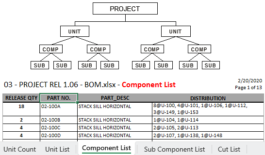
Gathering and Processing For this client, each Project includes any number of Units. Each Unit is made up of any number of Components, and each Component may or may not contain any number of Sub Components. Each of these is a seperate drawings file, which may reside in any one of several different folders. The process starts with each Unit drawing, then drilling down to find each Component and Sub Component, and gathering the information stored in each one. That information is then processed in several ways, and used to generate a five-worksheet Excel file with the formatted data. KCS Productivity Pack for AEC This program includes an extensive HTML based Help
system. Don't see anything like what you have in mind? Well, there was a first time for each of the examples shown above. They should at least give you some idea of the logical approach, user friendliness, and technology available at KCS for creating your solution.
|